


Description
Characteristics
3 Reviews
Description
Showing Slide 1 of 4
Enter BootLoader mode: Connect the USB-C cable, hold down the PRG button, press the RST button once, then release the PRG button.
- Replace a USB data cable.
- Change the port on the computer.
Austria, Belgium, Bulgaria, Croatia, Czech Republic, Denmark, Estonia, Finland, France, Germany, Hungary, Ireland, Italy, Latvia, Lithuania, Luxembourg, Malta, Netherlands, Norway, Poland, Portugal, Romania, Slovakia, Slovenia, Spain, Sweden, Switzerland, United Kingdom
South:
Alabama, Arkansas, Delaware, Florida, Georgia, Kentucky, Louisiana, Maryland, Mississippi, North Carolina, Oklahoma, South Carolina, Tennessee, Texas, Virginia, West Virginia
Midwest:
Illinois, Indiana, Iowa, Kansas, Michigan, Minnesota, Missouri, Nebraska, North Dakota, Ohio, Pennsylvania, South Dakota, Wisconsin
West:
Arizona, California, Colorado, Idaho, Montana, Nevada, New Mexico, Oregon, Utah, Washington, Wyoming
Northeast:
Connecticut, District of Columbia, Maine, Massachusetts, New Hampshire, New Jersey, New York, Rhode Island, Vermont
Not Supported:
Alaska, Hawaii, Puerto Rico
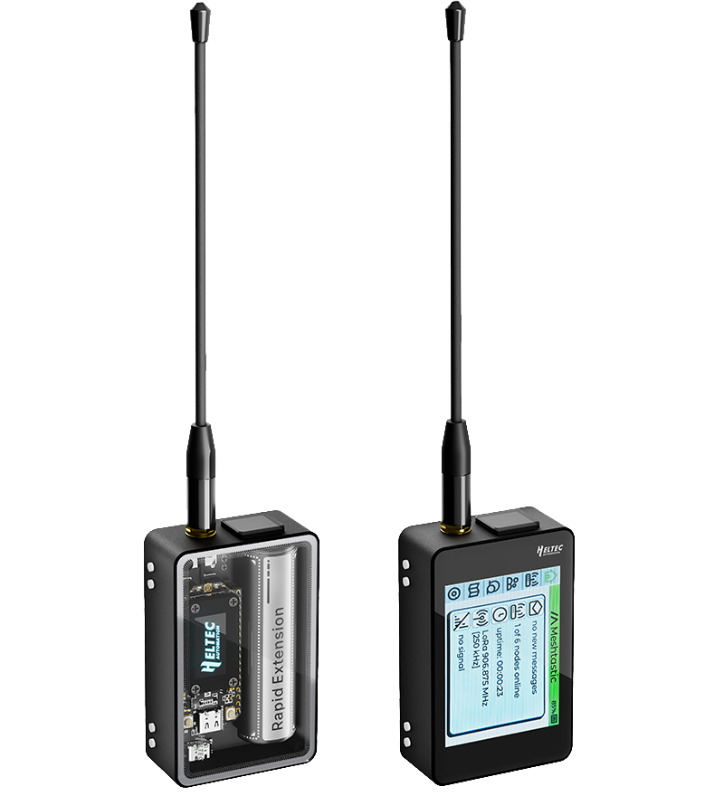
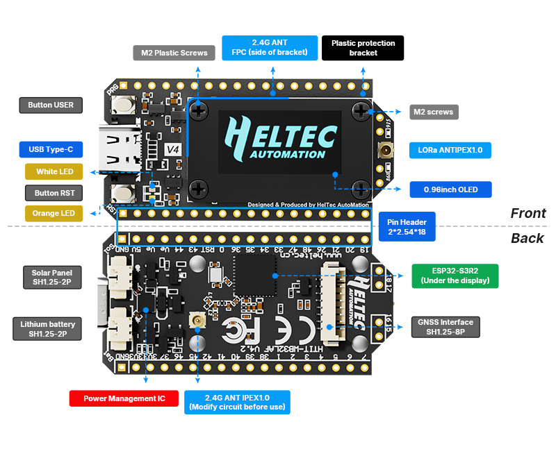
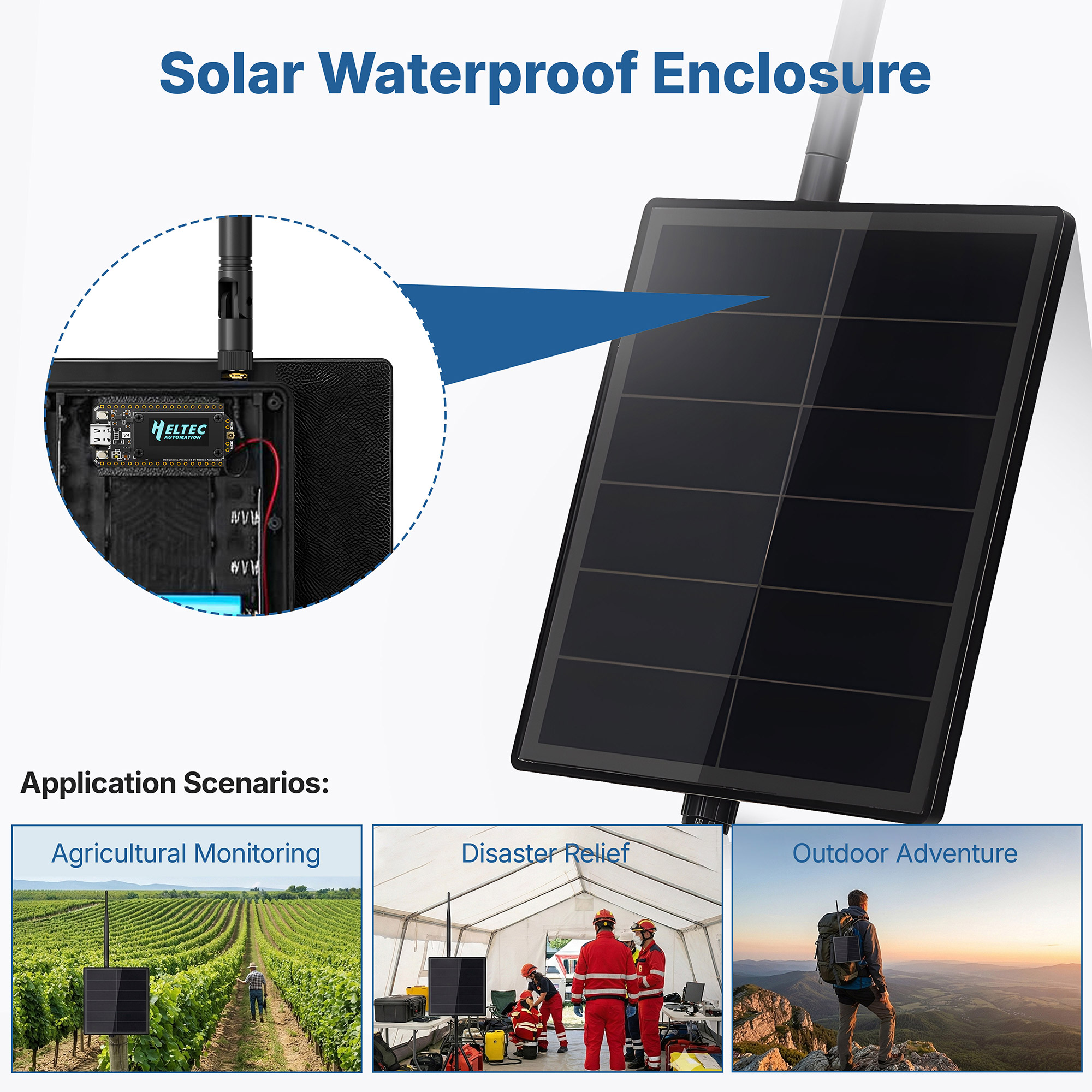
The default 2.4G FPC antenna is located on the side of the plastic screen bracket.
Hardware 4.2
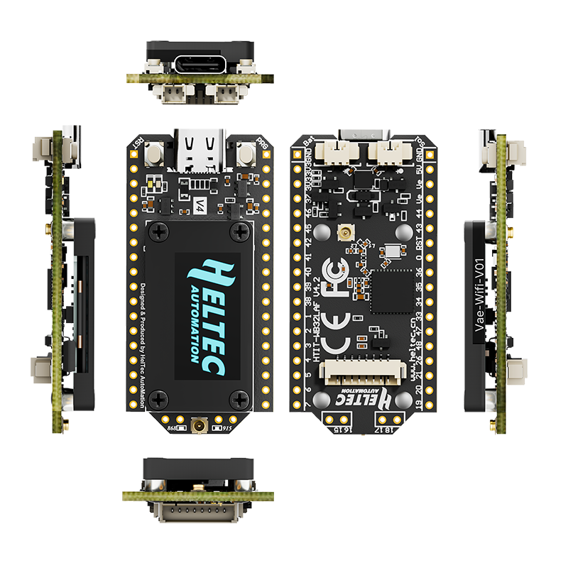
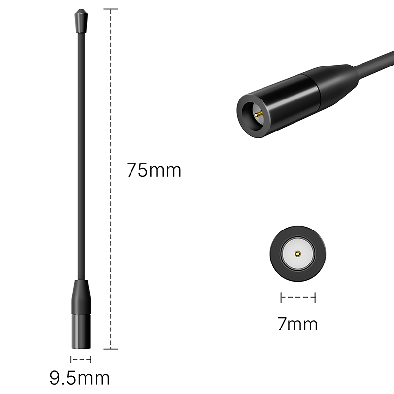
If you wish to use an IPEX-connected 2.4G antenna, you need to remove the inductor marked as ① in the diagram below, and add a 0-ohm resistor (or other conductive metal or cable) at the position marked ② to connect to the IPEX interface.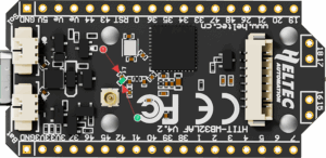
Hardware 4.3
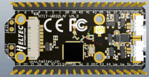
As shown in the figure below, Mark 2 indicates the default connection to the FPC antenna, while Mark 1 indicates the connection to the IPEX interface.
Why is it designed this way?
By default, it is connected to the onboard FPC, and its circuit has been tested to achieve optimal performance. When you switch the resistor to IPEX, the IPEX connector will achieve optimal performance.
If both the IPEX interface and the FPC contacts are connected at the same time, the communication performance on both sides will be degraded.
This is a 0-ohm resistor. If you don’t have high requirements for the 2.4G signal, you can directly use a soldering iron to short-circuit both directions at once, making both sides work simultaneously.
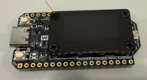
This area is attached with a 2.4G FPC antenna,and to avoid affecting its performance, customized plastic screws are used here.
That’s why they look different from ordinary screws.
When you need to remove it, gently press and turn with a screwdriver.
- Arduino
- Micro Python
- Platform.io
- Espressif IDE
We strongly recommend using Arduino. We have complete technical support and provide complete LoRaWAN code for ESP32 Arduino framework.
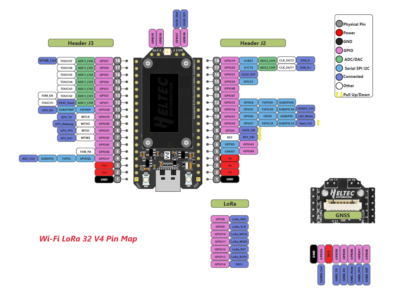
You can find this type of socket by search “SH1.25 x 2”.
Of course, you can contact our sales staff and provide your ideas.
They are compatible in most scenarios.
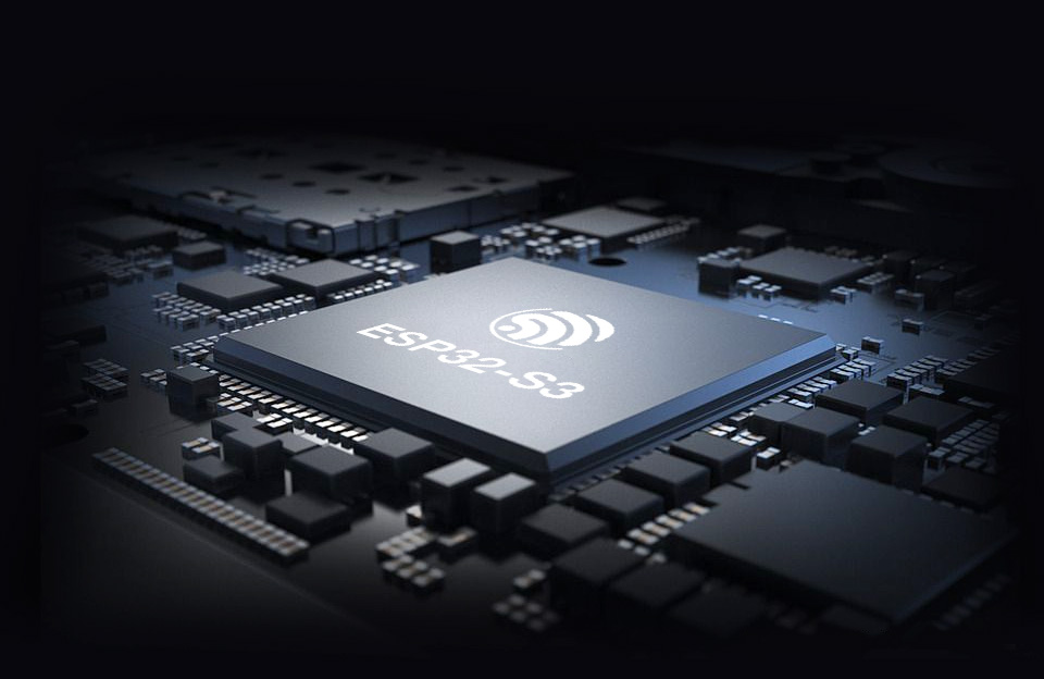
Since V4 uses the same series of chips as V3, features the same OLED, and has an almost identical pin layout, V3 and V4 can be used interchangeably in the majority of cases.
However, due to the increased transmit power, the transmit power settings in some code may no longer correspond directly to the actual output.
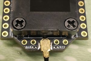
It indicates simultaneous support for both 868 MHz and 915 MHz frequency bands.
In the initial design, we developed two separate hardware versions to achieve optimal RF performance. However, through subsequent debugging, we have successfully unified the hardware for both 868 MHz and 915 MHz while maintaining excellent RF characteristics.
It does not indicate device damage. Please disregard this phenomenon. The LORA ERROR occurs because it is running the factory default LORA testing program and cannot find another device running the same program.
Hardware version 4.3 requires new firmware.
Note: The following content only applies to hardware V4.3 and above
- Meshtastic 2.7.20: On the device, use the PRG button to navigate to “System” → “LoRa”, where you can choose to enable or disable LNA.
- MeshCore 1.15.0: LNA is enabled by default and cannot be modified.
- You can download the firmware from this link, which has LNA disabled by default: LNA Disable
- With the firmware from this link, LNA can be toggled via button long press: LNA configurable
- We have submitted a PR. In the near future, official firmware will also support toggling LNA via command line or button.
Please note: “Meshtastic UI” is for use with the touchscreen. For ordinary OLED screens, please do not select it.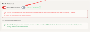
Dave Jones (verified owner) –
General Overview:
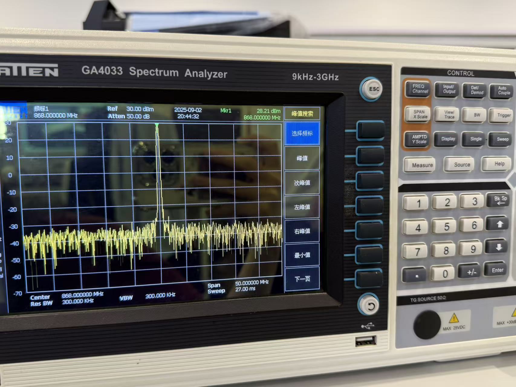
-The WiFi LoRa 32 (V4) delivers transmit power up to 28 ± 1 dBm.
-According to Heltec’s published testing, the V4 offers improved receiver sensitivity compared to earlier models.
-Includes expanded memory, featuring 2 MB PSRAM and 16 MB external Flash.
-Supports Wi-Fi (802.11 b/g/n), Bluetooth LE / BT5 / Mesh, and LoRa connectivity.
-Offers a solar input port.
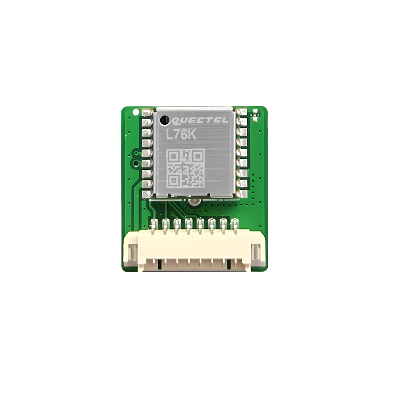
-Features a plug-and-play GNSS (GPS) interface on the underside of the board.
-Meshtastic firmware v2.7.13 provides full compatibility, and VNA testing has confirmed the board achieves its advertised transmit power using this firmware or greater.
When I purchased the WiFi LoRa 32 (V4) it was my first Heltec device after previously using LilyGO hardware. I was pleasantly surprised by the overall build quality. It’s clear that Heltec put some thought into the design, especially its compatibility with their optional WiFi LoRa 32 Expansion Kit.
I currently own two V4 units: one serves as a home base station connected to a rooftop antenna, and the second will likely become a portable node I carry with me. I’m also possibly considering using one in a solar-powered weather station project next summer. I would have to say this is a must have for beginners. Well there is always room from improvement like using a next generation radio, it checks most of the boxes meshtastic users currently require.
My experience buying directly from Heltec wasn’t perfect there were shipping delays during the initial launch week but customer service was responsive and the devices did arrive. For anyone ordering during high-demand periods like a devices day one launch, I’d keep in mind you should expect delays, or use third-party resellers like AliExpress or Amazon for potentially faster delivery.
Common User-Reported Issues:
-Some users would have preferred Heltec reversed the Battery and Solar connectors for better case compatibility; however this is a personal preference and as it stands does not affect device functionality.
-Due to GPIO layout changes relative to the previous WiFi LoRa 32 (V3), not all third-party accessories are backward compatible.
-Many V3 enclosures are not compatible with the V4 because of dimensional changes particularly because of the addition added OLED faceplate.
Info –
The correct email address is [email protected]
Tom Milledge (verified owner) –
I live in the U.S. I ordered 4 of the 902~928MHz band V4s and received 4 863-870MHz band V4s. I’ve sent two emails to [email protected] and still no response.